Perspective Drawing
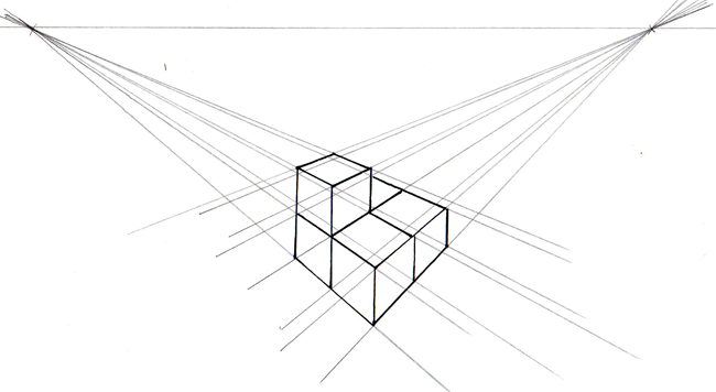
All cube edges which are vertical in the photo are vertical in the drawing. The line connecting the two vanishing points is horizontal.
The vertical edge of the central cube was drawn first - the height is an estimate. Then the construction lines from both vanishing points to both ends of this edge were drawn in.
The left and right bottom edges were then drawn in along the construction lines, again the lengths were estimated to give the impression of perspective. From these edges, the remaining vertical edges for the bottom layer of cubes can be drawn in.
Further construction lines are added between both vanishing points and all vertices.
Finally the upper layer cube was added, starting from the back right vertical, to ensure that the top rear edge of the lower layer of cubes would meet it appropriately.
The only property of the original construction preserved in this drawing are the vertical lines - and even they are not all the same length.
An advantage of this type of drawing is that it is possible to draw what you actually see. A disadvantage is that it is difficult to do well, and can take several attempts.
Given the hit and miss nature of this construction (the image above is my third attempt), you will not be surprised to learn that there is a mathematical way to calculate where all the vertices should be - this is called Projective Geometry.